It shouldn’t surprise you that you need some basic maths to understand how to add textures and materials to your creations in Blender.
In this part 1 article, using a simple triangle face, we will cover fundamentals that will lay a solid foundation for your understanding of Blender objects. We will cover normal vectors, the right hand grip rule, the vector cross product, face loops, face loop verteces, face loop half edges, and the mesh UV data structure.
We then probe the mesh, and UV data structure with python to validate everything we discussed.
We then briefly mention the default Blender UV unwrapping method – this is the process of projecting your 3D object on to a 2D UV plane.
Normal Vectors
No Clip?
Here is a curious thing. Once you import your simple triangle in to Unity not only will you find that you are unable to apply textures, but it is only visible from one side.
A 3D face is only visible on the side that corresponding to the normal vector pointing outbound from the face.
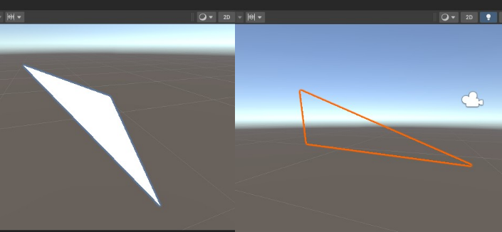
You won’t normally see this in games as 3D objects are constructed with many individual 3D faces that surround a 3D space completely.
Understanding the normal vector is critical to understanding how to add materials, textures, and UV mapping.
If you’ve heard the term “no clip” with reference to gaming I strongly suspect its origin is this “normal vector clipping” as the effect is very similar to the observation above.
Normal Vector Calculation
Right Hand Grip Rule
Let’s recap the construction of our simple triangle face. In python we stated,
vertices = [(0, 0, 0), (1, 0, 0), (0, 1, 0)]
tri_face = [(0, 1, 2)]
Where vertices A,B, and C are given by,
A=(0,0,0)
B=(1,0,0)
C=(0,1,0)
We then constructed a face by stating the ordering of the vertices that bound the face.
A -> B -> CVertex ordering is extremely important in Blender and is given the name vertex winding.
Thinking back to school you may have encountered the right hand grip rule. This is a quick and rough method to get the direction of the normal to the face/plane you just described.
Simply curve, or wind the fingers of your right hand in the direction of the order of the vertices you stated and your thumb will point in the direction of the normal vector. This is why it is called vertex winding in Blender.


The side of the face with the normal vector pointing out will be the side of the face visible in Unity.
Cross Product
Let’s go through more accurate calculation of the normal vector. We can calculate the normal vector by applying the vector cross product.
First we need to define our 3 edge vectors, AB,BC, and CA,


The cross product of any pair of these vectors will give the same normal vector result.
We’re going to stick with calculating the vector cross product AB x BC.
The general formula for calculating the cross product of two vectors is given by the determinate,
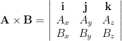
substituting for our vectors,
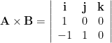
and expanding will give,
Normal = (0,0,1)This is the normal vector pointing directly up in the z-axis.
This is a very simple example, and for more complicated faces and angles in your 3D space you will get more complicated results that are not duplicates of the simple basis vectors.
For now, we know enough about normal vectors to further understand the application of materials and UV maps.
Face Loops, Half Edges, & Associated Loop Vertices
These items are very difficult to explain without first understanding the normal vector, since we already do… on we go.
In a Blender mesh data structure, each face is composed of one or more loops. A loop corresponds to a specific vertex on the face and contains information about the vertex itself, the (half) edge it is connected to, and information about its 3D to 2D UV image mapping.

Face Loop
Our single triangle face object has 3 loops, one loop associated with each edge AB, BC and CD.
Yup, each individual edge AB, BC or CD are referred to as a loop – it threw me too.
AB is an individual loop.
BC is an individual loop.
CD is an individual loop.
You can trust this, as later we will prove this with python.
Half Edge
Let’s consider the loop AB . As part of a larger 3D object our triangle face would be connected to another face and share an edge. Each face would have a loop that referenced it’s own half of that edge. This is where the term half edge comes from.
For the edge/loop AB the half edge is shown as a blue arrow. The red arrow would be the half edge connected to an adjacent face. There is a reason for the different directions in the arrows, more on this later.
Associated Loop Vertices
Not only does each loop have a half edge, it also has a specific vertex assigned to it. Of course, and edge has 2 vertices but only one is attached to the edge, more on which one is chosen and how it is chosen later.
UV Image Mapping Information
Once you have identified the 3D loop vertices you can map them to a 2D plane for ‘UV’ mapping, basically U,V coordinates between (0,0) and (1,1) on a plane that can represent an image.
How are Vertices, Half Edges and Loops Picked?
Short answer, using the normal vector and vertex winding. With a couple of simple rules even the most complex geometry will render out just fine.
- Step 1) Identify the normal vector.
- Step 2) Pick a vertex. This is now your loop vertex.
- Step 3) Move along an edge winding around in the direction relative to your normal vector.
This is now your half edge. - Step 4) Congratulations, you have created a loop composed of a vertex and its associated half edge.
- Step 5) Go back to step 2, move around your normal vector until you have discovered all vertices.
How Are 3D Mesh Vertices Mapped To 2D UV Layers?
Let simplify some of the jargon… UV Layers sounds like some UltraViolet light type mapping. It is not.
UV are just x,y coordinates on a 2D plane that could represent an image you want to wrap around your 3D object. Below on the left hand side you will see a simple 2D ‘UV map’.
On the right hand side you will see a 3D object. You can map the 3D points on the right with the 2D points on the left using the Blender GUI, or you can do this by using the Blender python API. There is some skill in getting this just right. Imagine trying to line up a flat 2D ‘UV map’ of a football to a 3D football shape? Fun times. You can do this in the ‘UV editing’ mode in Blender.
When creating a 3D object in the Blender GUI, a UV layer is automatically attached to the mesh… this is not so when building objects programmatically. Something to be aware of.
UV mapping… it’s like sprite sheets but for 3D objects. The ‘sprite sheet’ below is empty by the way.

Inspecting Mesh Face Loops Using Python
We’re going to prove all of the above by poking around Blender with the python API and expanding our previous simple triangle script.
We’re going to add code to the very end, past the point where you have finished the design of your 3D structure, and injected the descriptive data points from the BMesh data structure object in to the 3D world of your mesh.
We know that a UV data structure layer is not attached to our 3D object, so we are first going to create a new empty UV layer for our mesh. This is just an empty data structure that shadows 1:1 each vertex of our mesh.
# Create a new UV layer if it doesn't exist
if not mesh.uv_layers:
    mesh.uv_layers.new()
We then loop through and print out the data associated with our 3D sturcture using the following code,
# Loop through each face
for face in mesh.polygons:
    # Get the UV layer
    uv_layer = mesh.uv_layers.active.data
    # Loop through each loop of the face
    for loop_index in face.loop_indices:
        loop = mesh.loops[loop_index]
        vertex = mesh.vertices[loop.vertex_index]
        edge = mesh.edges[loop.edge_index]
        # Print loop attributes
        print("Loop Index:", loop.index)
        print("Vertex Index:", loop.vertex_index)
        print("Vertex Coordinates:", vertex.co)
        print("Edge Index:", loop.edge_index)
        print("Edge Coordinates:", [mesh.vertices[v].co for v in edge.vertices])
        print("UV Coordinates:", uv_layer[loop.index].uv)
        print("----------")
here is the code in full,
import bpy
import bmesh

# Create a new mesh
mesh = bpy.data.meshes.new("MyMesh")

# Create a new object and assign it to the mesh.
obj = bpy.data.objects.new("MyObject", mesh)

# Get a handle to the current scene in Blender.
scene = bpy.context.scene

# Link our object to the scene.
scene.collection.objects.link(obj)

# Create a BMesh data structure object.
bm = bmesh.new()

# Define the vertices coordinates and add them to the BMesh data structure.
v1 = bm.verts.new((0, 0, 0))
v2 = bm.verts.new((1, 0, 0))
v3 = bm.verts.new((0, 1, 0))

# Define a face by stating the bounding vertices and add to the BMesh data structure.
bm.faces.new((v1, v2, v3))

# Transfer the data in the BMesh data structure to the mesh.
bm.to_mesh(mesh)
# Clear and release the memory used by the BMesh data object.
bm.free()

# Create a new UV layer if it doesn't exist
if not mesh.uv_layers:
    mesh.uv_layers.new()

# Loop through each face
for face in mesh.polygons:
    # Get the UV layer
    uv_layer = mesh.uv_layers.active.data
    # Loop through each loop of the face
    for loop_index in face.loop_indices:
        loop = mesh.loops[loop_index]
        vertex = mesh.vertices[loop.vertex_index]
        edge = mesh.edges[loop.edge_index]
        # Print loop attributes
        print("Loop Index:", loop.index)
        print("Vertex Index:", loop.vertex_index)
        print("Vertex Coordinates:", vertex.co)
        print("Edge Index:", loop.edge_index)
        print("Edge Coordinates:", [mesh.vertices[v].co for v in edge.vertices])
        print("UV Coordinates:", uv_layer[loop.index].uv)
        print("----------")
running this python code gives the following output,
Loop Index: 0
Vertex Index: 0
Vertex Coordinates: <Vector (0.0000, 0.0000, 0.0000)>
Edge Index: 1
Edge Coordinates: [Vector((0.0, 0.0, 0.0)), Vector((1.0, 0.0, 0.0))]
UV Coordinates: <Vector (0.0000, 0.0000)>
----------
Loop Index: 1
Vertex Index: 1
Vertex Coordinates: <Vector (1.0000, 0.0000, 0.0000)>
Edge Index: 2
Edge Coordinates: [Vector((1.0, 0.0, 0.0)), Vector((0.0, 1.0, 0.0))]
UV Coordinates: <Vector (1.0000, 0.0000)>
----------
Loop Index: 2
Vertex Index: 2
Vertex Coordinates: <Vector (0.0000, 1.0000, 0.0000)>
Edge Index: 0
Edge Coordinates: [Vector((0.0, 1.0, 0.0)), Vector((0.0, 0.0, 0.0))]
UV Coordinates: <Vector (1.0000, 1.0000)>
----------
Considering the graph theory definition of a loop… man, it was confusing without digging deep in with python code. The python output confirms all the Blender concepts we stated above.

Notice that the loop, and vertex indexes in the python output match the sequential connectivity order but the edge indexes do not. This is because blender assigns edge indices based on the order in which the edges were created by Blender, not the sequential connectivity order we defined. Therefore, the edge with index 0 represents the CA edge, the edge with index 1 represents the AB edge, and the edge with index 2 represents the BC edge.
Notice that not only did blender create a mesh UV data structure, but if you look at the output of the UV Coordinates blender populated the data structure with coordinates that map out a perfect triangle on the UV map. This is the default Blender unwrapper in action.
Default Blender UV Unwrapping
Picture yourself taking a 2D bit of gift wrapping, and wrapping a 3D gift you are about to give to someone.
This in a nutshell is UV unwrapping / wrapping.
Blender creates UV coordinates for a mesh based on the default blender UV unwrapping method.
When you create a new mesh object, Blender automatically generates initial UV coordinates for each vertex.
In the case of the triangle face, Blender assumes a basic UV mapping by default. It assigns UV coordinates to the vertices of the triangle face in a way that matches the spatial positioning of the vertices in the 3D space. For example, in a counter-clockwise order, the UV coordinates might be assigned as (0, 0) for the first vertex, (1, 0) for the second vertex, and (1, 1) for the third vertex. This is a basic UV mapping that stretches the texture evenly across the triangle face.
Blender’s default UV unwrapping method is a simplistic and straightforward approach suitable for basic UV mapping needs. However, for more complex meshes or specific UV layouts, you may need to manually unwrap and adjust the UV coordinates to achieve the desired texture mapping.
It’s important to note that Blender provides various UV unwrapping techniques and tools to help you create more advanced and customized UV layouts for your meshes. These tools allow you to unwrap the mesh, adjust seams, manipulate UV islands, and optimize UV packing.
In summary, Blender generates initial UV coordinates for a triangle face based on a basic default mapping method, assuming a counter-clockwise order. However, for more complex UV mapping requirements, you can utilize Blender’s UV unwrapping tools to achieve the desired results.
Next Steps…
Now we have the some knowledge and intuition foundations, the next steps should be easy.
In the next article we will cover,
- Blender UV Unwrapping
- UV mapping
- Addition of object materials
[…] going to start with the basic python script we covered in part 1.We used this script to design and build a simple triangle face by defining 3D points in a data […]